Vandal-Resistant (IK10) Video Surveillance System Design Guide
A comprehensive engineering reference for designing anti-violence and anti-vandalism surveillance systems that are visible, hard to destroy, alarm when attacked, and preserve evidence even under damage. Covering IK10 camera selection, anti-tamper mounting, protected cabling, VMS alarm rules, redundancy, and O&M workflows.
System Overview
This guide defines an anti-violence and anti-vandalism (IK10) video surveillance design intended for sites where cameras may be intentionally blocked, struck, dismantled, spray-painted, cable-pulled, or bracket-destroyed. The objective is to build a system that is "visible + hard to destroy + alarms when attacked + preserves evidence even if damaged."
The system targets hostile or semi-hostile public-facing and controlled environments such as metro stations, underground passages, detention and custody zones, school critical areas, emergency rooms, psychiatric units, night-economy streets, construction entrances, and high-incidence public order points. It is grounded in IEC 62262 / EN 62262 standards, where IK10 implies resistance to 20 J impact energy under the standard test method.
Scope & Boundaries
Covers front-end camera selection (IK10+), anti-tamper mounting structures, anti-pull cabling, edge protection, event linkage, VMS rules, redundancy, storage integrity, and operational workflows. Not a substitute for full perimeter intrusion systems or physical security staffing.
Core Value Proposition
Reduces blind time from vandalism, increases attacker cost and effort, ensures "tamper-to-alarm" reaction within 3–10 seconds, and preserves admissible evidence with timestamps, logs, and export integrity verification.
Key Inputs
Site drawings (CAD), risk zoning, lighting data, mounting surfaces, cable routes, network/power availability, privacy constraints, retention requirements, and O&M capability assessment.
Typical Deliverables
Hostile-scene camera layout with redundant viewing; IK10+anti-tamper mounting details; tamper alarm rule sets; retention and bandwidth calculations; acceptance criteria and maintenance regime documentation.
System Architecture
The IK10 surveillance system is organized into four interdependent layers, each with distinct responsibilities and protection boundaries. The architecture ensures that even when the front-end edge is attacked, the system continues to record, alarm, and preserve evidence through layered redundancy and failover mechanisms.
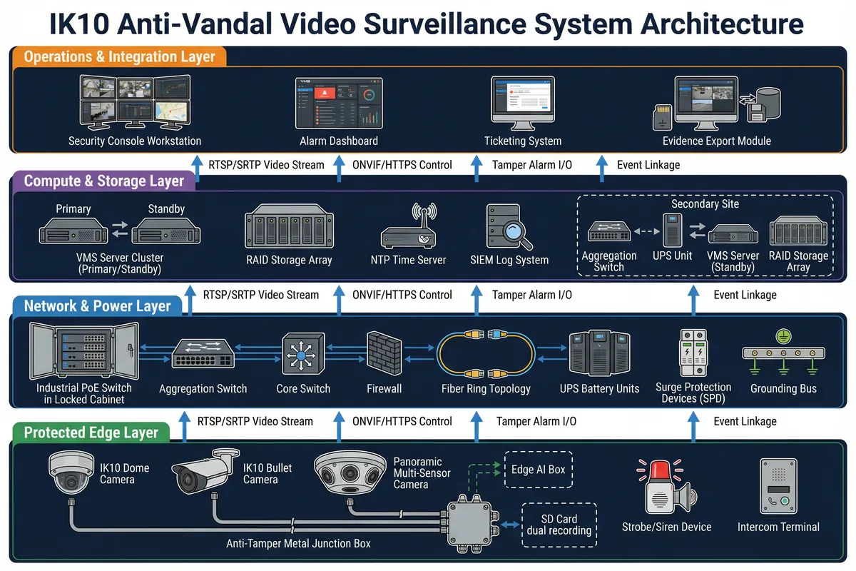
| Layer | Key Components | Primary Responsibility |
|---|---|---|
| Protected Edge Layer | IK10 cameras, anti-tamper mounts, metal conduit, junction boxes, strobe/siren, intercom | Withstand impact; detect occlusion/defocus; keep camera functional for identification and response |
| Network & Power Layer | Industrial PoE switches, aggregation/core switches, firewall, fiber ring, UPS, SPD, grounding | Keep connectivity during attacks; isolate security traffic; provide UPS-backed power; protect against surges |
| Compute & Storage Layer | VMS cluster (primary/standby), RAID storage, NTP, SIEM | Record reliably with integrity; provide search/export; handle failover; monitor device health and tamper events |
| Operations & Integration Layer | Security console, alarm workstation, ticketing system, evidence export module | Trigger response (guards, police, PA); manage incident workflow; preserve evidence chain |
Main Functions
The system is built around six core functional modules that form a closed "Anti-Vandal Evidence Loop." Each module contributes to the overall mission of deterrence, detection, continuity, and evidence preservation. The diagram below illustrates how these modules interconnect and reinforce each other.
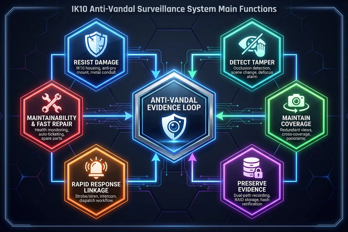
| Function | Value | Implementation | Acceptance Focus |
|---|---|---|---|
| Resist Damage | Reduces immediate loss of visibility | IK10 housings, anti-pry base, security screws, metal conduit, anti-pull strain relief | Physical inspection + impact/tug checks; no exposed cables |
| Detect Tamper | Alarms even when camera is blinded | Occlusion, scene-change, defocus detection; sensitivity tuning; debounce timers | Simulate tape/spray/flashlight; alarm within 3–10 s |
| Maintain Coverage | If one camera is destroyed, another records the act | Overlapping FoV, cross-coverage pairs, high-mount overview + low-mount ID | "Single camera loss test" still preserves face/body/route evidence |
| Preserve Evidence | Preserves footage if network is cut or NVR attacked | Camera SD card (encrypted) + central RAID; alarm clips on separate volume | Disconnect uplink; confirm local continues; verify backfill integrity |
| Rapid Response Linkage | Increases attacker cost and triggers response | Strobe/siren, voice prompts, intercom call pop-up, lighting boost, dispatch workflow | Tamper event triggers correct linked actions within SLA |
| Maintainability & Fast Repair | Reduces long-term blind spots from silent failures | Heartbeat, stream loss, storage health, UPS status; auto ticket creation; spare strategy | Device unplug test generates alarm + ticket; MTTR tracked |
Chapter Navigation
This guide is organized into twelve chapters, each addressing a distinct aspect of IK10 vandal-resistant surveillance system design, deployment, and operation. Use the navigation below or the left sidebar to jump directly to any chapter.
Key Dependencies & Assumptions
The design baseline assumes ONVIF-compatible IP cameras with a VMS capable of event ingestion, alarm rules, health monitoring, and evidence export with hashing. The threat model covers deliberate adversarial acts including occlusion, impact, prying, twisting, cable pull/cut, spray paint, laser blinding, and partial dismantling.
Critical Note on IK10 Misconception: IK10 alone does not stop dismantling, occlusion, or cable pull. The preferred approach (Option A) treats IK10 as one layer and enforces "device + structure + cabling + strategy + linkage." Budget-limited sites (Option B) should accept residual risks and mitigate with higher mounting, redundant views, and rapid repair SLAs.
| Dependency | Specification | Risk if Missing |
|---|---|---|
| Structured Cabling | Cat6A shielded in metal conduit; sealed junction boxes | Cable pull creates instant blind zone |
| PoE Switching | Industrial grade; PoE budget ≥ peak draw × 1.2 | Reboot loops at night (IR/heater load) |
| Fiber Uplinks | Dual-path or ring; SFP modules; OTDR-tested | Single cut = zone-wide blind area |
| UPS & Distribution | ≥30 min runtime for core; dedicated circuits | Power cut = recording gap |
| Surge Protection & Grounding | SPD at entry points; grounding resistance per local code | Lightning surge destroys ports/cameras |
| VMS with Health Monitoring | Tamper event handling; heartbeat; stream loss alerts | Silent failures go undetected for days |
| NTP Time Sync | Monitored; drift <1 s; all devices synchronized | Timestamp disputes invalidate evidence |
| Recording Policy | Minimum 30 days retention; continuous in critical zones | Evidence unavailable for investigation |