Tools & Accessories
Chapter 8 — Complete accessories checklist, installation tools, consumables, and spare parts requirements for IK10 vandal-resistant surveillance system deployment
8.1 Complete Accessories Checklist
A successful IK10 surveillance deployment requires a comprehensive set of accessories beyond the cameras and switches themselves. The accessories checklist below covers all 12 categories of materials required for a complete, code-compliant, anti-vandal installation. Omitting any category typically results in either a non-compliant installation or a future service call to retrofit the missing component — both of which are more expensive than including the accessory in the original bill of materials.
The checklist is organized by functional category and includes the minimum specification, quantity basis, and the consequence of omission. Quantities should be calculated based on the specific site survey, with a 10% overage allowance for consumables such as cable, conduit, and connectors.
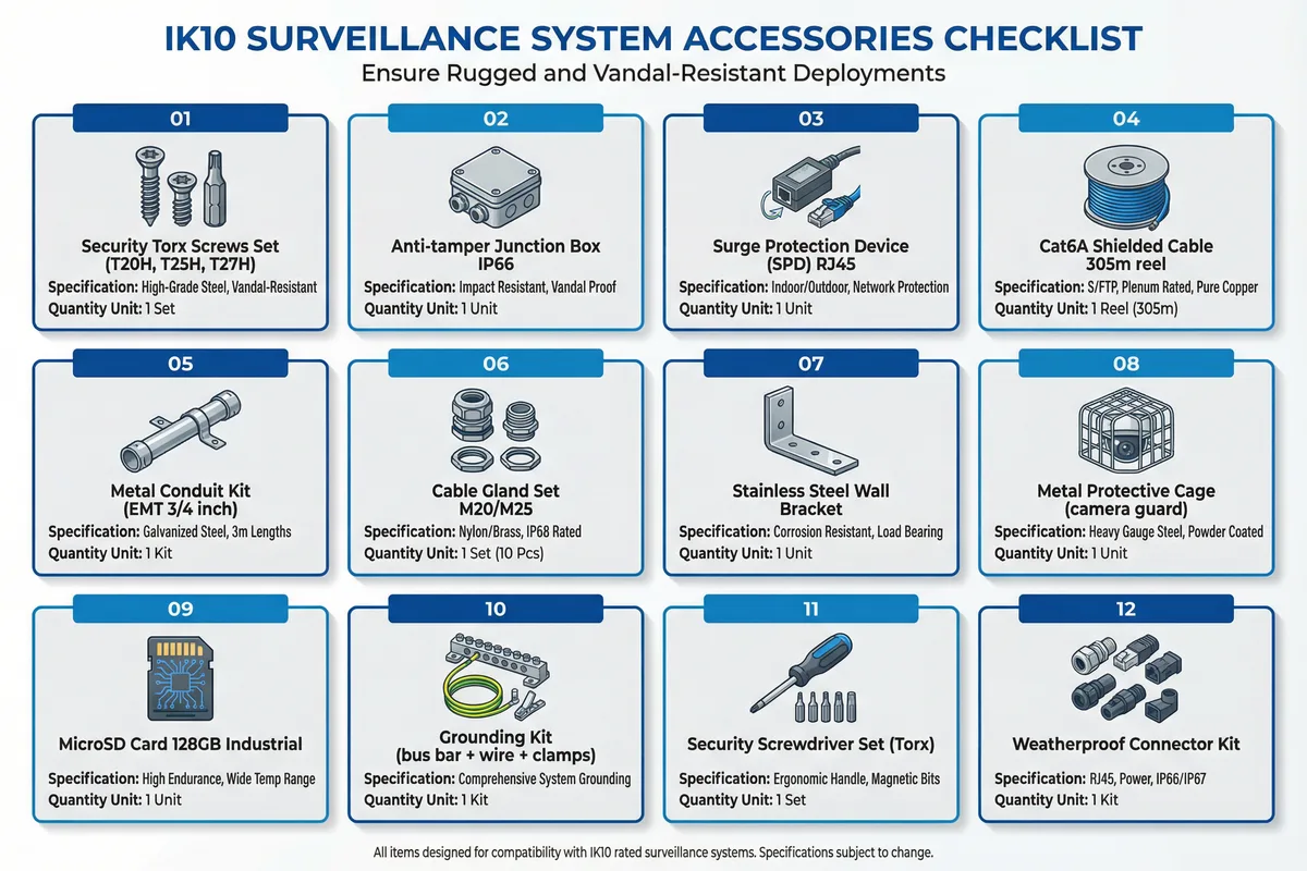
| # | Accessory | Specification | Quantity Basis | Consequence of Omission |
|---|---|---|---|---|
| 01 | Security Torx Screws Set | T20H, T25H, T27H; stainless steel A4 | 1 set per camera + 20% spare | Standard screws allow easy removal by attackers |
| 02 | Anti-tamper Junction Box IP66 | IP66/IK10; tamper switch; anti-pry; cable glands | 1 per camera installation point | Cable splice exposed; no tamper detection at cable entry |
| 03 | Surge Protection Device (SPD) RJ45 | IEC 61643-21; 10 kA; RJ45 in/out | 1 per outdoor cable entry; 1 per camera | Lightning/surge damage to camera and switch ports |
| 04 | Cat6A Shielded Cable | S/FTP; 23AWG; plenum-rated; 305 m reel | Measured cable run + 15% overage | Unshielded cable susceptible to EMI; reduced surge protection |
| 05 | Metal Conduit Kit (EMT 3/4") | Galvanized steel; 3 m lengths; fittings included | Measured conduit run + 10% overage | Exposed cable accessible for cutting or tampering |
| 06 | Cable Gland Set M20/M25 | IP68-rated; nylon or brass; 10-piece sets | 2 per junction box; 1 per conduit entry | Water ingress at cable entries; IP rating voided |
| 07 | Stainless Steel Wall Bracket | 316L stainless; anti-rotation pins; load-rated | 1 per camera (wall/ceiling mount) | Standard bracket removable with common tools |
| 08 | Metal Protective Cage | Heavy-gauge steel; powder-coated; replaceable lens cover | 1 per camera in reachable zones (<3.5 m) | Camera housing exposed to direct impact |
| 09 | MicroSD Card 128GB Industrial | Industrial grade; wide temp; endurance class | 1 per camera | No local backup recording during network outage |
| 10 | Grounding Kit | Bus bar; AWG 12 green/yellow wire; compression clamps | 1 kit per equipment cabinet + 1 per 8 cameras | Ground loops; surge damage; EMI interference |
| 11 | Security Screwdriver Set (Torx) | T20H, T25H, T27H bits; ergonomic handle; magnetic | 1 set per installation team | Unable to install/remove security screws |
| 12 | Weatherproof Connector Kit | RJ45 IP67; power IP66; heat-shrink solder sleeves | 2 per camera + 10% spare | Connector corrosion; intermittent connection failures |
8.2 Required Installation Tools
In addition to the accessories listed above, the installation team must be equipped with the appropriate tools to ensure a professional, compliant installation. The use of incorrect tools — particularly for cable termination and torque-critical fasteners — is a leading cause of premature installation failures and warranty voidance. The following table lists the minimum tool requirements for an IK10 surveillance installation team.
| Tool | Specification | Purpose | Critical Requirement |
|---|---|---|---|
| Cable Crimping Tool | RJ45 Cat6A; ratchet mechanism | Field-terminate Cat6A connectors | Ratchet mechanism ensures consistent crimp force |
| Cable Tester | Wiremap + length + PoE test | Verify cable continuity and PoE delivery | Must test PoE voltage at camera end, not just switch end |
| Torque Screwdriver | 0.5–5 Nm adjustable; Torx bits | Install security screws to specified torque | Over-torque strips threads; under-torque allows removal |
| Conduit Bender | EMT 3/4" and 1" sizes | Form conduit bends without kinking | Kinked conduit restricts cable pulling and traps water |
| Earth Resistance Tester | 4-wire Kelvin; 0.01–200 Ω range | Verify grounding resistance <1 Ω | Required for acceptance testing; document results |
| Laser Distance Meter | ±1.5 mm accuracy; 0.05–50 m range | Verify camera mounting height and coverage angle | Required for PPF (pixels per foot) verification |
| IP Rating Test Kit | Water spray nozzle per IEC 60529 | Verify IP66 rating of junction boxes after installation | Required for outdoor and wet-area installations |
Tool Calibration Requirement: The earth resistance tester and cable tester must have current calibration certificates (within 12 months) at the time of acceptance testing. Calibration records must be included in the as-built documentation package. Uncalibrated test equipment results are not acceptable for formal acceptance testing.