System Components
Chapter 1 — Component inventory, architecture, working principles, and mismatch risk analysis for IK10 vandal-resistant surveillance systems
1.1 System Architecture
The IK10 vandal-resistant surveillance system is structured as a multi-layer architecture where each layer has defined responsibilities, data flows, and protection boundaries. The architecture is designed so that an attack on the front-end edge does not compromise the ability of the system to record, alarm, and preserve evidence. Redundancy is built in at every critical junction — from dual-uplink fiber rings at the network layer to primary/standby VMS clusters at the compute layer.
The core deployment boundary encompasses IK10 front-end cameras, protected installation hardware, PoE network infrastructure, VMS with recording, UPS-backed power, network segmentation, and alarm rules. Optional extensions include edge AI analytics boxes for advanced behavioral detection, secondary recording locations for dual-path evidence preservation, and dual-site replication for mission-critical environments.
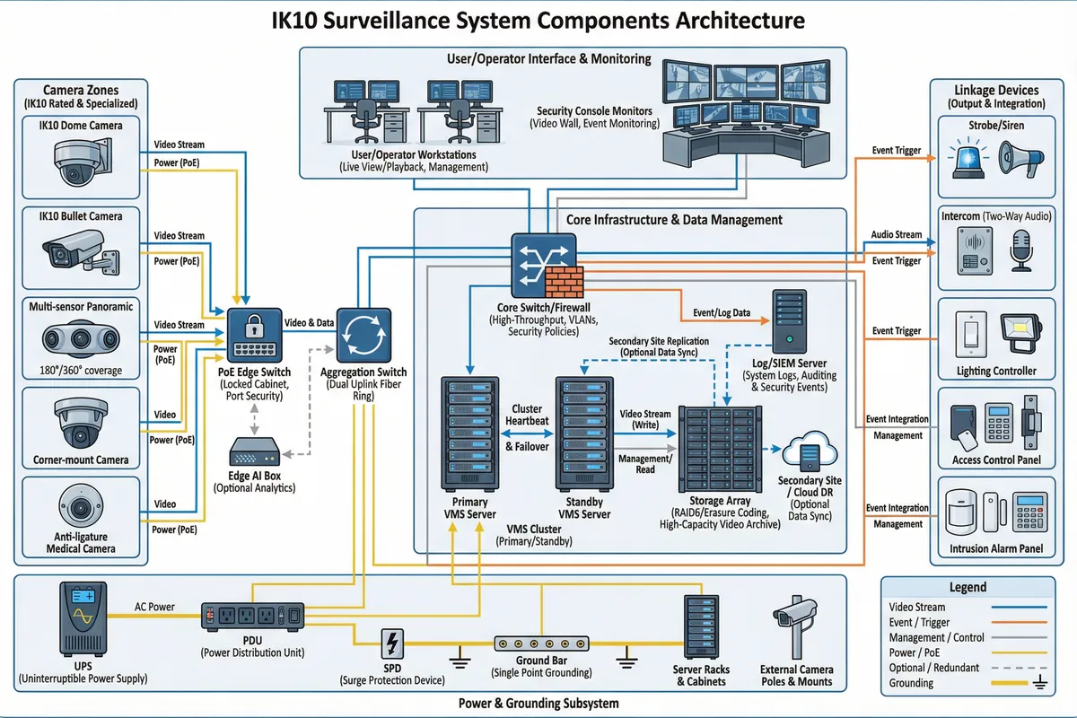
Data and Control Flows
- Video Stream: RTP/RTSP or vendor SDK → VMS ingest → storage write → indexing for search and playback
- Event Flow: Tamper/IO/analytics events → VMS rule engine → operator console + linkage devices (strobe, siren, intercom, access control)
- Management Flow: VMS/camera management via HTTPS/ONVIF over a dedicated management VLAN, isolated from camera traffic
- Power Flow: UPS → PDU → PoE switches and servers; SPD at all outdoor entry points → grounding bus → racks and poles
Deployment Boundaries
| Boundary | Components | Rationale |
|---|---|---|
| Core (Mandatory) | IK10 cameras, anti-tamper mounts, protected cabling, PoE network, VMS, RAID storage, UPS, alarm rules | Minimum viable system for deterrence, detection, and evidence |
| Optional (Enhanced) | Edge AI compute boxes, secondary recording site, dual-site VMS replication, acoustic sensors, anti-spray coatings | Extends capability for high-risk or mission-critical environments |
1.2 Components & Functions
The system comprises seven functional groups, each with distinct responsibilities, inputs, outputs, and key performance indicators. Understanding the role and failure modes of each component is essential for designing a system that performs reliably under adversarial conditions. The diagram below provides a grouped overview of all major components.
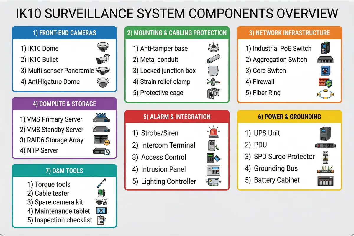
The table below provides a detailed breakdown of each major component category, including its responsibilities, inputs, outputs, key engineering KPIs, and the most common mismatch risk observed in field deployments.
| Component | Responsibilities | Inputs | Outputs | Key KPIs | Common Mismatch Risk |
|---|---|---|---|---|---|
| IK10 Dome Camera | Close-range identification, tamper detection | PoE power, network, lighting | Video stream, tamper events | IK10, IP66/67, WDR ≥120 dB, min illumination, tamper alarm latency | "IK10 only" but exposed cable; poor mount leads to pry-off |
| IK10 Bullet Camera | Longer-range view, perimeter lanes | PoE power, network | Video stream, events | IK10 or IK10 housing, long lens, stable bracket | Bracket not IK-rated; cable gland weak |
| Multi-sensor Panoramic | Wide coverage, reduce blind zones | PoE power, network | Multi-stream video | Coverage continuity, calibration stability, H.265 efficiency | Wrong height causes face pixel density too low |
| Anti-tamper Mount/Base | Resist pry/twist attacks | Structural substrate | Mechanical retention | Pull-out strength, corrosion resistance, torque spec | Mounted to weak substrate (decorative panel) |
| Protected Junction Box | Hide cable terminations; prevent access | Cable feeds | Sealed connections | IP66+ rating, anti-open tamper switch | Plastic box cracks; no tamper switch fitted |
| Industrial PoE Switch | Power and network edge distribution | AC/UPS input, fiber uplink | PoE ports, VLAN, events | PoE budget, surge tolerance, temperature range, ring protocol | Under-sized PoE budget causes reboot loops |
| VMS Servers (HA) | Stream ingest, alarm rules, user access control | Video streams, events | Recordings, alarms, exports | Failover time, max channels, rule engine capacity | Single point of failure; no standby configured |
| Storage RAID/EC | Retention and recording integrity | Write IO from VMS | Playback, export | Sustained write speed, rebuild time, SMART monitoring | Rebuild too slow; disk mismatch causes degraded performance |
| UPS + SPD + Grounding | Power continuity and surge protection | Mains AC power | Conditioned, protected power | Runtime, transfer time, SPD protection class | UPS not sized for PoE peak load (IR + heaters at night) |
| Strobe/Siren/Intercom | Deterrence and response linkage | Alarm trigger from VMS | Audio/visual deterrence, two-way audio | Activation latency, sound level (dB), IP rating | Not triggered by tamper events; wrong zone linkage |
Mismatch Consequences (Table 2)
| Mismatch | Failure Mechanism | Field Symptom | Impact | Prevention |
|---|---|---|---|---|
| IK10 camera + weak bracket | Bracket bends; camera re-aimed | View shifted; scene change alarm | Evidence lost from critical angle | Use IK-rated bracket + anti-rotation pins |
| Exposed pigtail cables | Cable pull/cut in seconds | Stream loss; camera offline | No recording from that camera | Concealed conduit to locked junction box |
| No tamper rules configured | Attack not detected by VMS | Silent blind spot | Delayed response; no alarm | Configure occlusion/scene-change alarms with debounce |
| No redundancy coverage | Single camera loss = blind zone | Attacker unseen after destruction | Low deterrence; evidence gap | Overlapping FoV + cross-coverage pairs |
| Storage without write margin | Burst traffic drops frames | Gaps in footage | Evidence gap at critical moments | Size storage IO with ≥30% headroom |
1.3 Working Principle
The system operates through three distinct phases: startup, normal operation, and exception/recovery. Understanding these phases and the exception chains they trigger is critical for configuring alarm rules, testing acceptance criteria, and training operators.
Startup Sequence
The startup sequence follows a strict dependency order: UPS comes online first, ensuring power stability before any network or camera equipment boots. PoE switches then boot and begin providing power to cameras. Cameras receive power, establish network links, obtain IP addresses (DHCP or static), and synchronize time via NTP. The VMS then registers all camera streams and applies recording schedules. Finally, tamper analytics are armed and alarm rules become active.
Normal Operation
During normal operation, the system performs continuous or event-based recording depending on the risk profile of each zone. Health polling runs continuously — monitoring PoE draw, stream availability, storage write health, UPS battery status, and cabinet door events. Alarms are displayed on the operator console with priority routing. Evidence export is controlled by role-based permissions with full audit logging.
Exception Chains
Exception Chain 1 — Occlusion (tape/cloth/spray): Image histogram collapses → scene change detected → defocus increases → camera tamper event fires → VMS correlates with adjacent witness camera → immediate strobe/siren + operator pop-up + incident ticket → bookmark pre/post event clips. Recovery: onsite removal/cleaning; verify lens integrity; adjust sensitivity if false positives occur.
Exception Chain 2 — Cable Pull or Cut: PoE power drop or link down → switch port down alarm + camera offline alarm → adjacent camera continues recording → VMS flags "critical blind area" → dispatch with route guidance. Recovery: inspect conduit/junction; replace cable; verify shielding/ground; test PoE class draw.
Exception Chain 3 — Bracket Sabotage (twist/aim shift): Camera orientation changed → scene-change detected → scene-change alarm fires → adjacent camera captures suspect → optional gyro/angle sensor triggers additional alert. Recovery: re-align camera; add anti-rotation pins; torque-check all fasteners; consider higher mount or cage.
| Phase | Key Actions | Failure Indicator | Recovery Mechanism |
|---|---|---|---|
| Startup | UPS → PoE → Camera → NTP → VMS → Analytics armed | Camera not registering; NTP drift | Auto-reconnect; template re-apply |
| Normal Operation | Continuous recording; health polling; alarm display; export control | Stream loss; storage write error | Alert + auto reconnect; standby VMS takeover |
| Uplink Failure | Ring reroutes; VMS standby takes over; storage controller failover | Multiple cameras offline; ring alarm | Ring protocol reroutes within seconds |
| Camera Replacement | Auto-provision templates applied; tamper re-armed | New camera not provisioned | Camera template library; DHCP reservation |