Design Methods
Chapter 2 — Executable design principles, failure analysis, decision logic, key dimensions, and KPI framework for IK10 vandal-resistant surveillance systems
2.1 Executable Principles & Basis
Effective IK10 surveillance design is grounded in twelve executable principles derived from threat modeling, structural mechanics, cybersecurity practice, and field incident analysis. These principles are not aspirational guidelines but engineering requirements with verifiable acceptance criteria. Each principle is paired with a design basis that explains why it matters in adversarial environments.
1. Design for Adversary Time-Cost
Raise the effort needed to blind or destroy cameras. Every second an attacker spends increases exposure. Basis: threat modeling + field incidents.
2. IK10 is Necessary, Not Sufficient
Include anti-pry mounts, anti-pull cabling, and anti-occlusion detection. IK10 alone cannot stop dismantling or cable cut. Basis: failure analysis.
3. No Exposed Weak Points
Hide pigtails, screws, and connectors. Every exposed component is a potential attack vector. Basis: common attack vector analysis.
4. Cross-Coverage by Default
Every critical view has a witness view. If one camera is destroyed, another records the act and suspect trajectory. Basis: resilience design.
5. Tamper-to-Alarm Within 3–10 Seconds
Define and enforce alarm latency targets. Fast alarms enable fast response. Basis: operational response SLA requirements.
6. Two-Stage Evidence Preservation
Local buffer (SD card) + central recording for critical zones. Protects against link-cut scenarios. Basis: link-cut failure analysis.
7. Install Strength > Device Strength
Mount to structural substrate, not decorative panels. The weakest point determines the system's physical resilience. Basis: structural mechanics.
8. Minimize Maintenance Friction
Use standard fasteners, camera templates, and spare pools. Fast repair reduces blind time. Basis: maintainability engineering.
9. Security by Segmentation
Isolate camera VLAN, enforce least privilege, use certificates. Cyber attacks can disable recording as effectively as physical attacks. Basis: cybersecurity practice.
10. Measure What Matters
Track pixel density, retention completeness, alarm SLA, and MTTR. What is not measured cannot be improved. Basis: acceptance testing.
11. Environmental Hardening
Apply IP rating, corrosion resistance, vibration tolerance, and thermal margin. Environmental stress compounds adversarial damage. Basis: environmental engineering.
12. LCC Optimization
A cheaper camera with frequent replacement costs more over 5 years. Total cost of ownership includes truck rolls, downtime, and evidence gaps. Basis: lifecycle cost logic.
2.2 Failure Causes → Recommendations
Field deployments consistently reveal the same failure patterns. The table below maps each root cause to its failure mechanism, the recommended engineering countermeasure, and the verification method that confirms the fix has been properly implemented. These pairs represent the most impactful improvements available to designers and installers.
| Failure Cause | Failure Mechanism | Recommendation | Verification |
|---|---|---|---|
| "IK10 camera, normal screws" | Screws removed quickly with common tools | Security screws (Torx pin / tri-wing) + hidden fasteners | Attempt removal with standard tools; should fail |
| Cable exposed under camera | Pull/cut in seconds; no tools needed | Conduit to locked junction box; strain relief clamp | Visual inspection + tug test on cable |
| Camera mounted too low | Reachable by hand; easy to grab and twist | Mount height policy (≥3.5 m) + protective cage where low ceiling | Measure height; simulate reach test |
| Over-sensitive tamper detection | False alarms cause operator fatigue; alarms ignored | Profile-based thresholds + debounce timers; day/night profiles | One-week alarm statistics; false alarm rate within threshold |
| No lighting consideration | Face not identifiable at night; evidence unusable | Add supplemental lighting, WDR tuning, IR planning | Pixel density measurement at night; face ID test |
| Single uplink edge switch | One cut = entire zone blind | Dual uplink or ring topology; RSTP/ERPS protocol | Pull one uplink; verify reroute within seconds |
| Storage sized only for average load | Burst traffic drops frames at critical moments | IO headroom ≥30% + write cache; size for peak not average | Stress test sustained write; verify no frame drops |
| No spare/repair SOP | Long outage; extended blind zone | Spare camera pool + toolkits + documented SLA | Drill MTTR exercises; measure against P1/P2/P3 targets |
2.3 Core Design / Selection Logic
The design decision process follows a structured sequence that begins with risk zoning and ends with acceptance test planning. The decision tree below provides a visual guide for selecting the appropriate camera type, mounting method, cabling approach, recording mode, and linkage level based on the specific characteristics of each zone.
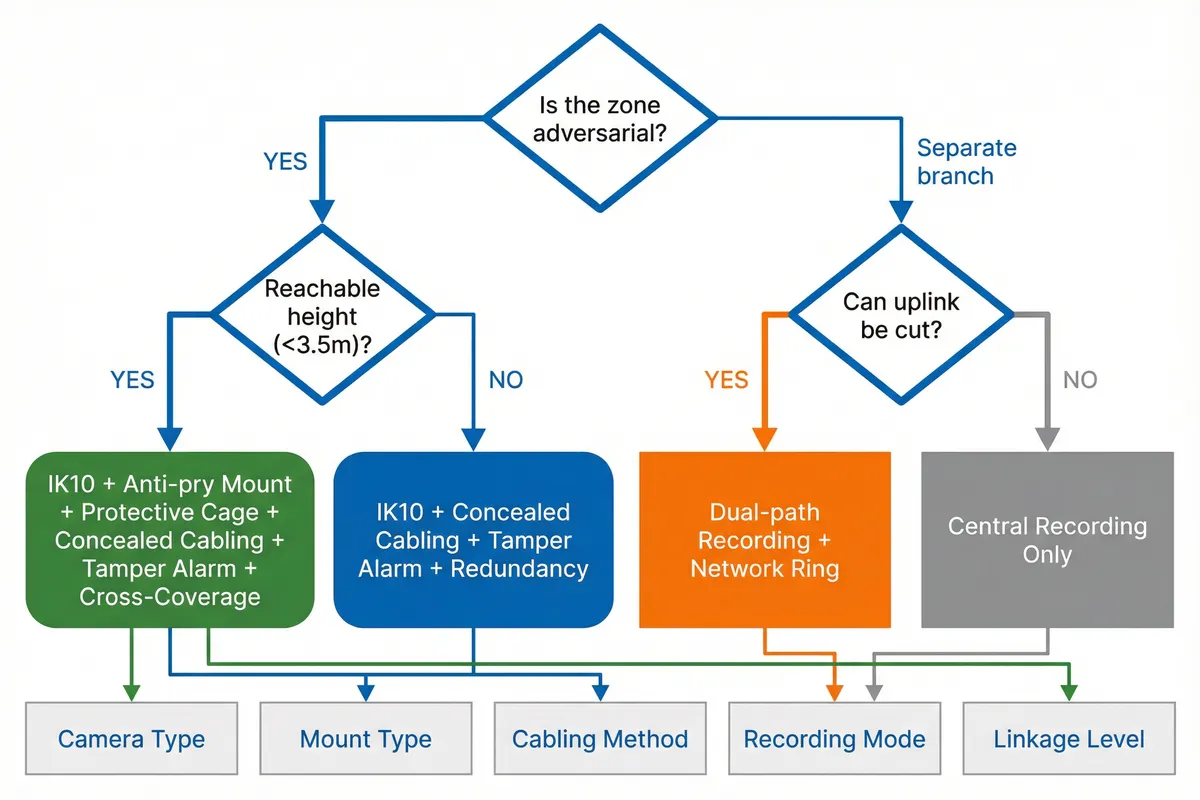
Step-by-Step Design Sequence
- Risk Zoning: Classify each area by threat level (adversarial / semi-adversarial / standard) and reachability (height, access control)
- Coverage & Pixel Density Targets: Define PPF requirements for identification (150–250 PPF) vs. overview (30–80 PPF) at each choke point
- Reachable vs. Non-reachable Mounting: Determine mounting height; add cages or recessed housings for reachable zones
- Anti-pull Cabling Route: Plan conduit paths; identify junction box locations; specify strain relief and sealing requirements
- Tamper Detection Profile: Configure occlusion, scene-change, and defocus sensitivity per zone; set debounce timers
- Redundancy Design: Assign witness cameras; define cross-coverage pairs; plan panoramic placement for overview
- Network/Power Resilience: Size PoE budget; plan dual uplinks or ring; size UPS for peak load × runtime target
- Storage Retention & Integrity: Calculate TB requirement with overhead factor; define RAID level; plan hot spares
- Acceptance Tests & O&M: Define test cases for each function; document SLAs; plan spare inventory and inspection schedule
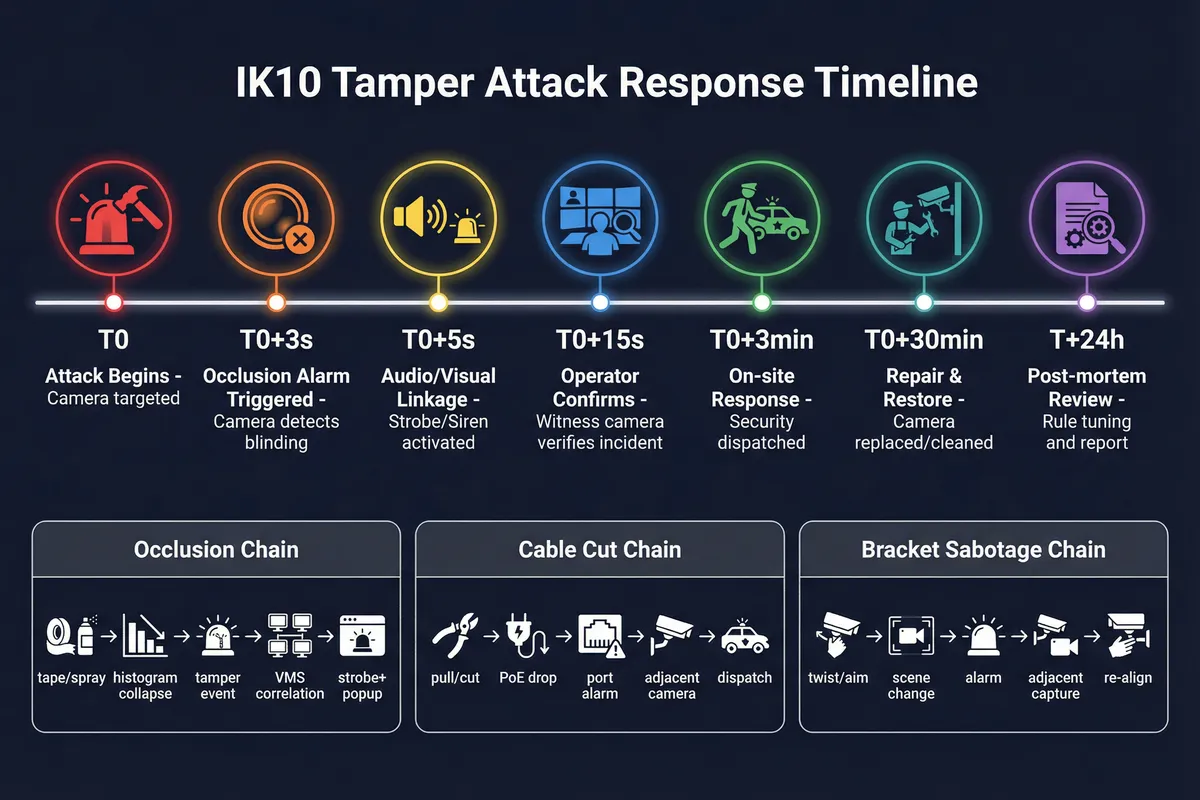
Response Timeline Reference: T0 attack begins → T0+3s occlusion alarm → T0+5s strobe/siren linkage → T0+15s operator confirms via witness camera → T0+3min on-site response → T0+30min repair and restore → T+24h post-mortem and rule tuning.
2.4 Key Dimensions
Effective design requires balancing seven key dimensions simultaneously. Each dimension has a primary optimization target, a typical metric, and a trade-off control mechanism. The table below provides a structured framework for making design decisions that account for all relevant dimensions rather than optimizing for a single factor.
| Dimension | What to Optimize | Typical Metric | Trade-off Control |
|---|---|---|---|
| Performance / UX | Identification quality and search speed | PPF at choke points, search latency, time-to-find | Indexing, presets, UI optimization |
| Reliability | Continuous recording without gaps | Uptime %, failover time, recording gap rate | HA architecture, ring topology, UPS |
| Maintainability | Fast replacement and repair | MTTR, standard parts availability | Camera templates, spare pool, SOP |
| Compatibility | Multi-vendor interoperability | ONVIF profiles verified, API coverage | Lab test matrix before deployment |
| LCC (Lifecycle Cost) | 5-year total cost of ownership | 5-year TCO including truck rolls and downtime | Reduce replacements; invest in quality mounts |
| Energy Efficiency | PoE and server power consumption | W/camera, kWh/year, PoE budget utilization | H.265 codecs, efficient IR, smart scheduling |
| Compliance | Privacy and audit requirements | Access log completeness, masking coverage | Policy enforcement; regular privacy audits |