Support & Integration
Chapter 7 — Supporting systems, third-party integration requirements, VMS platform compatibility, and ecosystem dependencies for IK10 vandal-resistant surveillance deployments
7.1 Supporting Systems Overview
An IK10 vandal-resistant surveillance system does not operate in isolation. Its effectiveness depends critically on the quality and integration depth of eight supporting system categories, each of which contributes a distinct capability to the overall security posture. The diagram below illustrates all supporting systems and their bidirectional data flows with the central IK10 surveillance hub. A weakness in any supporting system can undermine the entire "resist + detect + preserve + respond" chain.
The integration design must address not only the technical interfaces between systems but also the operational workflows: who receives which alerts, in what format, with what priority, and what actions are expected in response. A technically perfect integration that generates too many false alarms or requires complex operator actions will be disabled or ignored in practice, negating its security value.
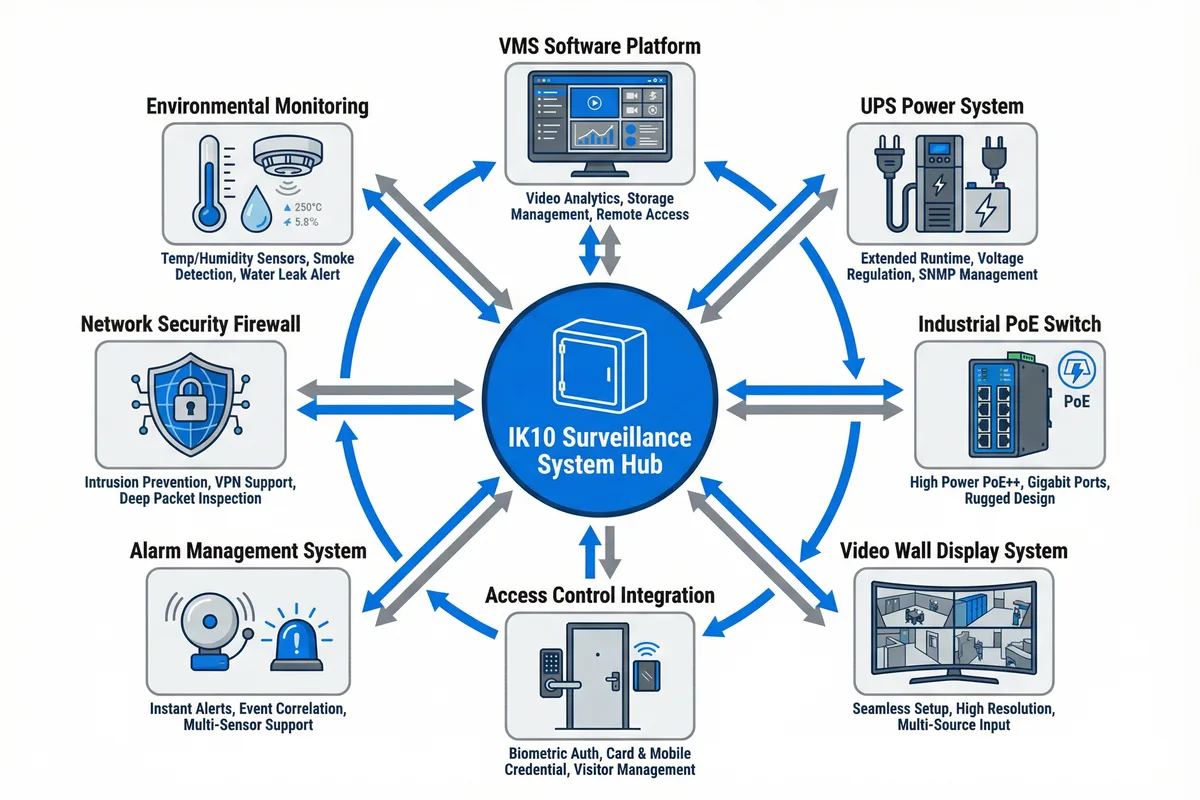
| Supporting System | Primary Function | Integration Interface | Dependency Level | Failure Impact |
|---|---|---|---|---|
| VMS Software Platform | Video recording, analytics, event management | ONVIF, RTSP, proprietary SDK | Critical | No centralized recording; cameras record to SD only |
| UPS Power System | Power continuity during mains failure | SNMP (APC/Eaton MIB); dry contact | Critical | System offline during power failure; evidence gap |
| Industrial PoE Switch | Power + network distribution to cameras | SNMP, LLDP, web management | Critical | All cameras on switch go offline |
| Access Control System | Door/gate control; credential management | SDK, REST API, Wiegand, OSDP | High | No automatic door-camera correlation; manual review only |
| Alarm Management System | Event correlation, dispatch, escalation | SDK, REST API, ONVIF event | High | Alarms not dispatched; response delayed |
| Video Wall Display | Real-time monitoring; incident response | HDMI, DVI, RTSP decode | Medium | No live monitoring; recording continues |
| Network Security Firewall | Network segmentation; intrusion prevention | Syslog, SNMP, management API | High | Surveillance VLAN exposed to corporate network |
| Environmental Monitoring | Temperature, humidity, smoke, water detection | Modbus, BACnet, SNMP, dry contact | Medium | No early warning of equipment room hazards |
7.2 VMS Platform Integration Requirements
The Video Management System (VMS) is the central integration hub for the IK10 surveillance system. All cameras, storage, analytics, and alarm systems connect through the VMS, which provides the unified operator interface, event correlation engine, and evidence management workflow. VMS selection must be based on the specific integration requirements of the deployment, including camera count, analytics requirements, third-party system integrations, and evidence export workflow.
| Requirement Category | Minimum Requirement | Recommended | Verification Test |
|---|---|---|---|
| Camera Protocol Support | ONVIF Profile S | ONVIF Profile S/T/G + proprietary SDK | Add camera via ONVIF; verify stream and PTZ |
| Tamper Alarm Handling | Receive and display ONVIF tamper events | Auto-popup video + dispatch + escalation | Trigger occlusion; verify alarm in VMS within 10 s |
| Evidence Export | Export to MP4 with timestamp overlay | Export with SHA-256 hash + audit log entry | Export clip; verify hash and audit trail |
| Redundancy | Manual failover to standby VMS | Automatic failover <30 s; no recording gap | Kill primary VMS; verify standby takes over |
| Storage Management | Configurable retention per camera | Per-camera retention + legal hold flag | Set 30-day retention; verify oldest footage overwrites |
| Access Control Integration | Manual correlation (separate systems) | Automatic door-camera correlation; unified timeline | Badge access event; verify camera popup in VMS |
| Analytics | Motion detection | Perimeter intrusion + loitering + face detection | Walk through detection zone; verify alert within 5 s |
| Cybersecurity | HTTPS management; role-based access | LDAP/AD integration; MFA; audit log | Attempt unauthorized access; verify blocked and logged |
7.3 Power System Requirements
The power system is the most critical supporting system for an IK10 surveillance deployment. A power failure that takes down the surveillance system at the same time as a physical security incident creates the worst possible outcome: the incident occurs but there is no evidence. Power system design must therefore be treated as a security requirement, not merely an operational convenience.
| Component | Specification | Sizing Rule | Monitoring Requirement |
|---|---|---|---|
| UPS (Online Double-Conversion) | IEC 62040-3 Class 1 (VFI) | Total load × 1.5 × runtime factor | SNMP; battery health; runtime remaining |
| Battery Runtime | ≥30 min at full load | Size for longest expected outage + 20% margin | Monthly runtime test; annual battery replacement |
| Surge Protection Device | IEC 61643-11 Type 2 | One SPD per cable entry from outdoors | Visual indicator; replace after surge event |
| Grounding System | IEC 60364-5-54; resistance <1 Ω | Single-point grounding; no ground loops | Annual resistance measurement; document results |
| Power Distribution Unit | Monitored PDU with per-outlet metering | One PDU per equipment rack/cabinet | Per-outlet current; total load; SNMP alerts |
UPS Sizing Example: For a deployment with 16 cameras at 15W each (PoE), 2 PoE switches at 50W each, and 1 NVR at 100W, the total load is (16 × 15) + (2 × 50) + 100 = 440W. With a 1.5× safety factor, the UPS must be rated for at least 660W / 825VA. For 30-minute runtime at 440W, the battery capacity must be at least 440W × 0.5h / 0.85 (inverter efficiency) = 259 Wh. A typical 1000VA/900W online UPS with extended battery module provides approximately 45 minutes at this load.