Installation & Debugging
Chapter 11 — Step-by-step installation requirements, mounting procedures, cable management standards, and commissioning/debugging protocols for IK10 vandal-resistant surveillance systems
11.1 Installation Requirements
IK10 anti-vandal surveillance camera installation requires a higher standard of workmanship than standard IP camera installation. The installation quality directly determines whether the IK10 rating provides its intended protection: a correctly rated camera incorrectly installed can be defeated just as easily as a standard camera. The installation requirements below are mandatory for all IK10 deployments and must be verified during acceptance testing.
The photograph below illustrates a compliant IK10 installation in a transit corridor, showing the correct mounting height, conduit routing, junction box placement, and security fastener usage. This serves as the visual reference standard for all IK10 installations in this deployment.
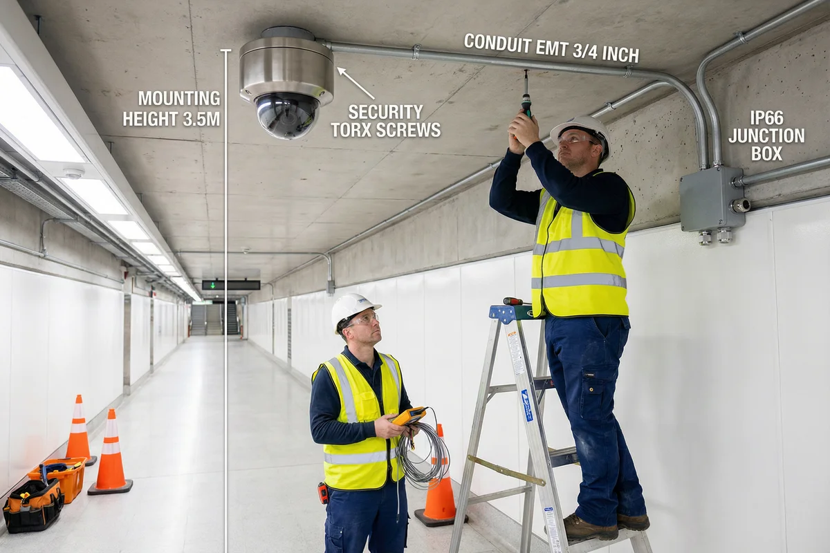
| Requirement | Standard | Specification | Verification |
|---|---|---|---|
| Mounting Height | Mandatory | 2.5–4.5 m above finished floor; 3.0–3.5 m optimal for face identification | Laser distance measurement; document per camera |
| Mounting Surface | Mandatory | Concrete, masonry, or steel structure; minimum pull-out strength 500 N per anchor | Anchor pull-test; torque verification |
| Security Fasteners | Mandatory | Security Torx T25H or T27H; stainless steel A4; torque to manufacturer spec (typically 2.5–3.5 Nm) | Torque screwdriver verification |
| Anti-Rotation | Mandatory | Anti-rotation pins installed; camera cannot be rotated by hand after installation | Manual rotation test: must not move |
| Cable Protection | Mandatory | 100% of cable in EMT 3/4" metal conduit from camera to secure area; no exposed cable runs | Visual inspection; photo documentation |
| Junction Box | Mandatory | IP66/IK10 rated; tamper switch installed; cable glands IP68; anti-pry design | IP spray test; tamper switch function test |
| Surge Protection | Mandatory | RJ45 SPD (10 kA) at each outdoor cable entry; grounded per IEC 61643-21 | Visual inspection; continuity test |
| Grounding | Mandatory | Camera housing grounded; single-point ground; resistance <1 Ω | 4-wire earth resistance measurement |
| Protective Cage | Required if height <3.5 m | Heavy-gauge steel cage; powder-coated; replaceable polycarbonate lens cover | Visual inspection; impact test |
| Camera Aim | Mandatory | Aimed per coverage design; PPF ≥40 at face-identification distance; no lens flare from light sources | PPF measurement; live image review |
11.2 Mandatory Installation Sequence
The installation sequence for IK10 cameras must follow the order below to ensure that each step can be verified before it is covered by subsequent work. Deviating from this sequence — for example, pulling cable before conduit is installed — creates situations where non-compliant work cannot be detected during acceptance testing. The sequence is mandatory for all IK10 installations.
- Site Survey & Marking: Mark all camera positions on walls/ceilings with chalk. Verify mounting surface structural integrity. Confirm cable route from each camera to the equipment room. Mark all conduit routing with chalk line.
- Conduit Installation: Install EMT 3/4" metal conduit along all marked routes. Install conduit straps at maximum 1.5 m intervals. Install conduit fittings at all bends and junction points. Verify conduit is continuous from camera position to equipment room. No conduit runs may be left open.
- Junction Box Installation: Install IP66/IK10 junction boxes at each camera position. Install tamper switch wiring. Install cable glands in all conduit entry points. Verify tamper switch operation before closing box.
- Surge Protection Device Installation: Install RJ45 SPD at each outdoor cable entry point. Connect SPD ground wire to building ground. Verify SPD ground continuity.
- Cable Pulling: Pull Cat6A S/FTP cable through conduit from equipment room to each camera. Leave 300 mm service loop at each camera position. Label both ends of each cable with camera ID. Test cable continuity and wiremap before termination.
- Camera Bracket Installation: Install stainless steel bracket at each camera position using security Torx fasteners. Verify anchor pull-out strength. Install anti-rotation pins. Verify bracket cannot be rotated by hand.
- Camera Installation & Aiming: Mount camera to bracket. Connect Cat6A cable to camera RJ45 port. Verify PoE power-up. Aim camera per coverage design. Verify PPF at face-identification distance. Lock camera aim with set screws.
- Protective Cage Installation (if required): Install protective cage over camera. Verify cage does not obstruct camera field of view. Install cage fasteners with security Torx screws.
- Equipment Room Termination: Terminate all cables at PoE switch patch panel. Label all patch panel ports. Connect PoE switch to NVR/VMS. Verify all cameras appear in VMS.
- System Configuration & Hardening: Complete hardening checklist for each camera. Configure recording schedules, retention periods, and analytics. Configure tamper alarms and escalation. Verify all alarms function correctly.
- Formal Acceptance Testing: Complete all 12 acceptance tests per Chapter 10. Document all results. Obtain customer sign-off on acceptance test record.
11.3 Common Faults & Debugging Procedures
The following table documents the most common installation faults encountered in IK10 surveillance deployments, their root causes, diagnostic steps, and corrective actions. This table should be used as a first-line reference by commissioning engineers during the debugging phase and by maintenance technicians during the operational phase.
| Fault Symptom | Root Cause | Diagnostic Step | Corrective Action |
|---|---|---|---|
| Camera not powering up | PoE budget exceeded; cable fault; SPD failure | Measure PoE voltage at camera; check switch budget; bypass SPD | Upgrade switch; replace cable; replace SPD |
| Blurry image | Lens contamination; focus drift; condensation | Clean lens; check focus setting; check IP seal | Clean lens with IPA; re-focus; reseal housing |
| Image too dark at night | IR LEDs failed; IR range exceeded; IR blocked by cage | Check IR LED status in VMS; measure distance; check cage clearance | Replace camera; reduce distance; adjust cage |
| Tamper alarm false triggers | Vibration from nearby machinery; wind movement | Review alarm log timing; check mounting rigidity | Increase tamper sensitivity threshold; add vibration isolation |
| Recording gaps | SD card failure; network packet loss; VMS overload | Check SD card health; measure packet loss; check VMS CPU | Replace SD card; fix network; upgrade VMS server |
| Camera offline after rain | Water ingress at cable gland or junction box | Inspect junction box seals; check cable gland tightness | Replace cable glands; reseal junction box; dry out camera |
| Ground loop interference (horizontal lines) | Multiple ground paths; ground potential difference | Measure voltage between camera ground and switch ground | Implement single-point grounding; install ground isolation transformer |
Safety Warning: Never open an IK10 camera housing while the camera is powered. Always disconnect PoE power at the switch before opening the housing for maintenance. Failure to do so risks electric shock and will void the camera warranty. Always use the correct security Torx bit to avoid stripping the security fasteners — stripped fasteners must be drilled out and replaced, which is a costly and time-consuming repair.