Quality & Acceptance
Chapter 10 — IK10 certification verification, image quality benchmarks, acceptance testing procedures, and quality comparison standards for vandal-resistant surveillance deployments
10.1 IK10 vs. Standard Camera Quality Comparison
The most compelling argument for specifying IK10-rated cameras is not the abstract impact resistance rating but the real-world performance difference after exposure to the vandalism and environmental stresses that occur in high-risk deployments. The comparison below illustrates the typical outcome after 12 months of operation in a transit environment: a standard polycarbonate dome camera versus an IK10 stainless steel dome camera installed side-by-side under identical conditions.
The quality gap extends beyond physical housing integrity. IK10 cameras are typically designed with higher-grade optical components, wider operating temperature ranges, and more robust electronics that maintain image quality under the same adverse conditions that destroy standard cameras. The total cost of ownership calculation must account for replacement frequency, labor costs, and — critically — the security gaps created by failed cameras.
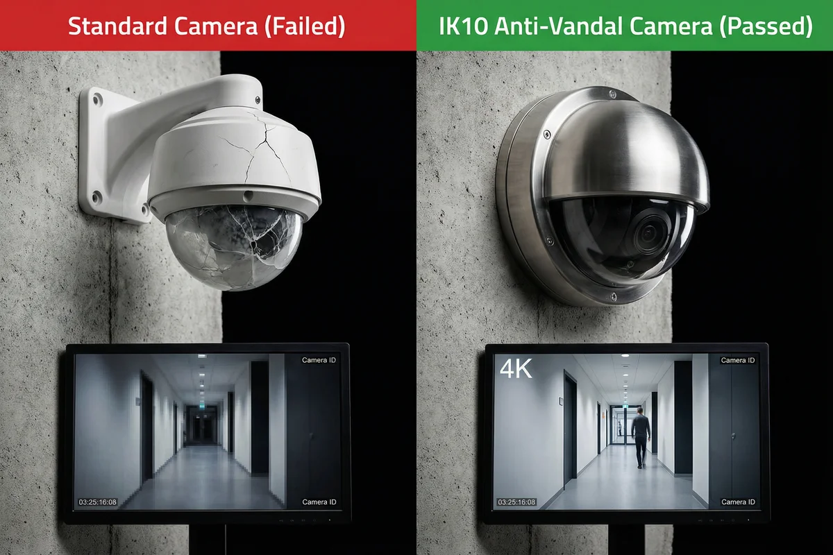
| Quality Dimension | Standard Camera (IK07 or lower) | IK10 Anti-Vandal Camera | Impact on Security |
|---|---|---|---|
| Housing Integrity | Cracked/shattered dome after impact; housing deforms | No visible damage after IK10 test (20J); maintains IP rating | Failed camera creates evidence gap; IK10 continues recording |
| Image Quality After Impact | Lens misalignment; blurred image; condensation ingress | Lens protected; image quality unaffected | Blurred footage inadmissible as evidence; IK10 footage usable |
| IP Rating Retention | IP66 voided after housing crack; water/dust ingress | IP66/IP67 maintained; sealed construction | Corrosion failure in outdoor/wet environments |
| Operating Temperature | -10°C to +50°C typical | -40°C to +60°C (industrial grade) | Standard camera fails in extreme cold/heat; IK10 operates |
| MTBF (Mean Time Between Failures) | 25,000–40,000 hours typical | 50,000–80,000 hours (industrial components) | Standard camera requires 2–3× more frequent replacement |
| Tamper Detection | Typically absent or basic motion-based | Built-in tamper alarm; housing open detection | No alert when standard camera is attacked; IK10 alerts immediately |
| Mounting Security | Standard Phillips/Pozidrive screws | Security Torx screws; anti-rotation pins; anti-pry design | Standard camera removable in <60 s; IK10 requires specialized tools |
| 5-Year TCO (16 cameras) | $8,000–$15,000 (replacements + labor) | $1,200–$2,400 (minimal replacements) | IK10 delivers 5–10× lower 5-year TCO in high-risk environments |
10.2 Formal Acceptance Testing Procedures
Formal acceptance testing is the process by which the customer verifies that the installed system meets all contractual and technical specifications before accepting the system and releasing final payment. For IK10 surveillance systems, acceptance testing must cover four domains: physical installation quality, image quality, functional performance, and cybersecurity baseline. Each test must be documented with pass/fail results, test conditions, and the name of the testing engineer.
| # | Test Item | Test Method | Pass Criterion | Documentation |
|---|---|---|---|---|
| T01 | IK10 Housing Verification | Visual inspection + certificate review | IK10 certificate from accredited lab; no housing damage | Certificate copy in as-built package |
| T02 | IP Rating Verification | Visual inspection of seals + water spray test | No water ingress after 1-min spray per IEC 60529 | Photo evidence; test date/engineer |
| T03 | Mounting Security | Torque test on all visible fasteners | All fasteners at specified torque; security Torx confirmed | Torque values recorded per camera |
| T04 | Cable Protection | Visual inspection of conduit and junction boxes | 100% of cable in metal conduit; all boxes IP66; no exposed cable | Photo evidence per camera run |
| T05 | Image Quality (PPF) | Test chart at specified distance; measure PPF | ≥40 PPF at face-identification distance for all cameras | PPF measurement per camera; chart photo |
| T06 | Night Vision Performance | Test in total darkness; measure recognition distance | Face recognition at ≥50% of specified IR range | Night-mode screenshot per camera |
| T07 | Tamper Alarm Function | Manually occlude lens; check alarm in VMS | Alarm received in VMS within 10 seconds | VMS alarm log screenshot |
| T08 | Recording Continuity | Simulate network outage; verify SD card recording | Recording continues to SD card; no gap >5 s | SD card footage review |
| T09 | PoE Power Verification | Measure PoE voltage at camera; check switch budget | PoE voltage 44–57V at camera; switch budget <80% utilized | Voltage measurement per camera |
| T10 | Cybersecurity Baseline | Verify hardening checklist per camera | All 8 hardening items confirmed; no default passwords | Signed hardening checklist per camera |
| T11 | UPS Runtime Test | Disconnect mains; measure runtime at full load | System operates ≥30 min (or specified runtime) on UPS | Test duration recorded; load measurement |
| T12 | Grounding Resistance | 4-wire earth resistance measurement | Ground resistance <1 Ω at all measurement points | Resistance values per measurement point |
Acceptance Documentation Package: The as-built documentation package must include: (1) as-built drawings showing actual camera positions and cable routes, (2) completed acceptance test record for all 12 tests, (3) IK10 and IP rating certificates for all camera models, (4) signed hardening checklist for every camera, (5) calibration certificates for all test equipment, and (6) VMS configuration backup. This package must be delivered in both digital and printed form and retained for the system lifetime.