Architecture Design
Chapter 4 — Typical system topology, device wiring, network design, storage architecture, and redundancy strategies for IK10 vandal-resistant surveillance systems
4.1 Typical System Topology
The IK10 vandal-resistant surveillance system is organized as a three-tier hierarchical network topology, with a dedicated power and grounding subsystem running in parallel. This architecture ensures that a single point of failure at any tier does not result in a complete loss of recording or alarm capability. The topology is designed to be scalable from small single-building deployments to large multi-site campus systems.
The core design principle is that every critical data path has at least two routes: fiber ring or dual uplinks at the distribution layer, primary/standby VMS at the compute layer, and local SD card backup at the edge layer. This "defense in depth" approach ensures that even a deliberate attack on the network infrastructure does not create a complete evidence gap.
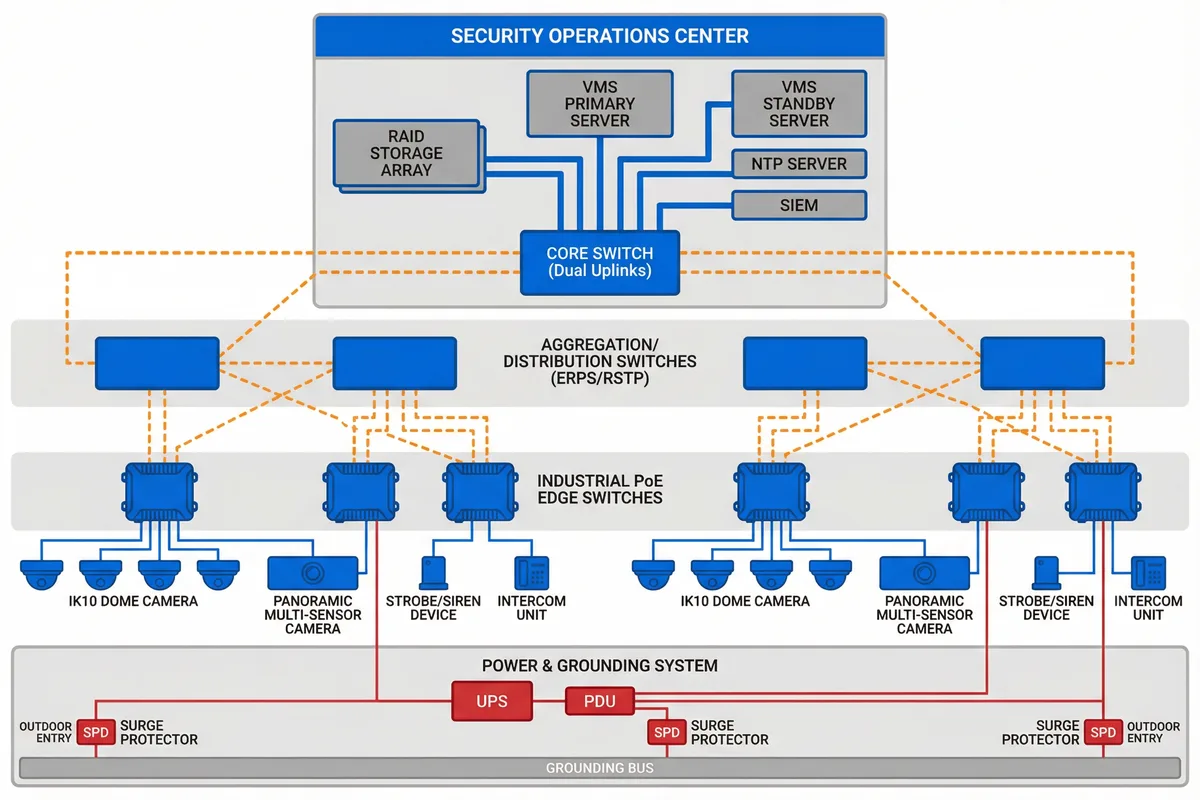
| Tier | Components | Connectivity | Redundancy Mechanism | Failure Impact |
|---|---|---|---|---|
| Core/Data Center | Core switch, VMS primary/standby, RAID storage, NTP, SIEM | 10G/40G backbone; dual power feeds | VMS active/standby failover; RAID rebuild; dual PSU | Standby VMS takes over within 30 s; no recording gap |
| Distribution/Aggregation | Aggregation switches (2–4 per zone) | Fiber ring (ERPS/RSTP); dual uplinks to core | Ring protocol reroutes within 50 ms | Single switch failure: ring reroutes; no outage |
| Edge/Access | Industrial PoE switches, IK10 cameras, strobe/siren, intercom | Cat6A PoE to cameras; SFP uplink to distribution | Camera SD card local recording; PoE switch UPS-backed | Single camera offline: SD records locally; adjacent camera continues |
| Power & Grounding | UPS, PDU, SPD, grounding bus | Dedicated circuits; SPD at outdoor entry points | UPS ≥30 min runtime; bypass mode | Mains failure: UPS maintains recording for ≥30 min |
Deployment Scale Options
| Scale | Camera Count | Typical Topology | VMS Architecture | Storage |
|---|---|---|---|---|
| Small (Single Zone) | 8–32 cameras | Single PoE switch + single aggregation switch | Single VMS server + NAS | RAID-5 NAS, 30 days |
| Medium (Multi-Zone) | 32–128 cameras | 2–4 edge switches + 2 aggregation switches + fiber ring | Primary + standby VMS + dedicated storage | RAID-6 storage, 30–60 days |
| Large (Campus/Multi-Site) | 128–1000+ cameras | Full three-tier with dual-site replication | VMS cluster + distributed storage + SIEM | Erasure coding, 60–90 days |
4.2 Device Wiring Diagram
The device wiring diagram illustrates the physical connections between a single IK10 camera installation point and the supporting infrastructure. Every connection is specified with cable type, maximum distance, and protection requirements. The wiring design follows the principle that no cable should be exposed or accessible without tools, and every connection point should be sealed against moisture and protected against surge.
The junction box is a critical component in the anti-vandal wiring design. It serves as the transition point between the exposed camera pigtail and the protected conduit run. The junction box must be IP66-rated, mounted with anti-tamper screws, and include a tamper switch that triggers an alarm if the box is opened. All cable entries must be sealed with appropriate cable glands.
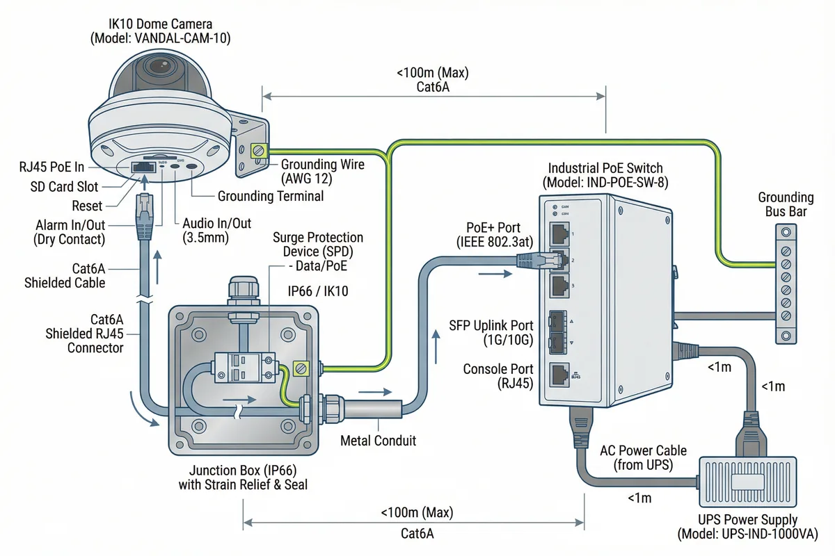
| Connection | Cable Type | Max Distance | Protection | Notes |
|---|---|---|---|---|
| Camera to Junction Box | Cat6A shielded, pigtail | ≤3 m (exposed) | Metal conduit from junction box | Pigtail must be shortest possible; no slack loops |
| Junction Box to PoE Switch | Cat6A shielded, 23AWG | ≤100 m | Metal conduit; SPD at entry point | Shielded cable required for outdoor/exposed runs |
| Grounding Wire | AWG 12 green/yellow | Shortest path | N/A | Camera bracket → grounding bus; resistance <1 Ω |
| PoE Switch to Aggregation | OM3/OM4 fiber or Cat6A | ≤300 m (fiber) / ≤100 m (copper) | Fiber preferred for long runs | SFP modules; OTDR-tested after installation |
| Power (UPS to Switch) | 3-core power cable, 1.5 mm² | ≤10 m from PDU | Dedicated circuit; no shared with lighting | UPS output → PDU → switch; no extension cords |
Anti-Pull Design Rule: The cable must be anchored with a strain relief clamp inside the junction box, so that a pull force on the cable outside the box is transferred to the clamp, not to the RJ45 connector or camera port. The strain relief clamp must be rated for ≥50 N pull force. The conduit must be anchored to the wall or structure at intervals ≤500 mm to prevent the conduit itself from being pulled away.
4.3 Network Design Requirements
The network design for an IK10 surveillance system must address four key requirements simultaneously: sufficient bandwidth for all camera streams, network segmentation for security, redundancy for resilience, and quality of service (QoS) for alarm traffic prioritization. These requirements often conflict with each other and must be balanced based on the specific site constraints and risk profile.
VLAN Segmentation
All surveillance traffic must be isolated in dedicated VLANs to prevent unauthorized access and ensure that a compromise of the IT network does not affect surveillance recording. The minimum VLAN structure includes a camera data VLAN, a management VLAN, and an alarm/event VLAN. Cross-VLAN traffic is permitted only through the firewall with explicit allow rules.
| VLAN | Purpose | Traffic Type | Access Control |
|---|---|---|---|
| VLAN 10 — Camera Data | Video stream transport | RTP/RTSP, high bandwidth | Cameras only; VMS as receiver |
| VLAN 20 — Management | Camera configuration and health | HTTPS, ONVIF, SNMP, NTP | VMS and admin workstation only |
| VLAN 30 — Alarm/Event | Alarm and event signaling | Low bandwidth, high priority | VMS, alarm console, dispatch |
| VLAN 40 — Corporate IT | General office traffic | Mixed | No access to surveillance VLANs |
Bandwidth Planning
Bandwidth planning must account for peak simultaneous recording, event-triggered high-quality streams, and management traffic overhead. The standard formula uses the per-camera bitrate multiplied by the camera count, with a 30% overhead factor for retransmissions, management traffic, and burst events. Storage IO must be sized separately with a 30% headroom above the sustained write rate.
| Camera Type | Resolution | Codec | Typical Bitrate | Peak Bitrate |
|---|---|---|---|---|
| IK10 Dome (Standard) | 4MP | H.265+ | 2–4 Mbps | 6–8 Mbps (event) |
| IK10 Dome (High-End) | 8MP | H.265+ | 4–6 Mbps | 10–12 Mbps (event) |
| Panoramic Multi-sensor | 4×4MP | H.265+ | 8–12 Mbps | 16–20 Mbps (event) |
| IK10 Bullet (Face Capture) | 4MP | H.265+ | 3–5 Mbps | 8–10 Mbps (event) |
4.4 Storage Architecture & Redundancy
The storage architecture for an IK10 surveillance system must provide three guarantees: continuous recording without gaps, integrity verification for evidence admissibility, and rapid access for incident investigation. These requirements drive the choice of RAID level, hot spare strategy, write cache configuration, and backup policy.
| RAID Level | Min Drives | Fault Tolerance | Write Performance | Recommended Use |
|---|---|---|---|---|
| RAID-5 | 3 | 1 drive failure | Good | Small deployments, ≤32 cameras |
| RAID-6 | 4 | 2 drive failures | Moderate | Medium deployments, 32–128 cameras |
| RAID-10 | 4 | 1 drive per mirror pair | Excellent | High-write alarm-clip storage |
| Erasure Coding (EC) | 6+ | Configurable | Good (distributed) | Large deployments, 128+ cameras |
Evidence Integrity Requirement: All exported evidence clips must be accompanied by a SHA-256 hash generated at export time and logged in the VMS audit trail. The export process must be role-restricted (supervisor authorization required) and the exported file must include embedded metadata: camera ID, timestamp, export user, and hash value. This chain of custody documentation is required for legal admissibility in most jurisdictions.