Selection & Interfaces
Chapter 5 — Core product introduction, interface logic, selection criteria, and functional comparison tables for IK10 vandal-resistant surveillance equipment
5.1 Core Product Introduction
The IK10 vandal-resistant surveillance product ecosystem comprises five core product categories, each engineered to address specific aspects of the anti-vandal design challenge. Understanding the capabilities, limitations, and selection criteria for each product category is essential for building a system that achieves the "resist + detect + preserve + respond" objective. The photograph below shows the five core product categories in a typical deployment configuration.
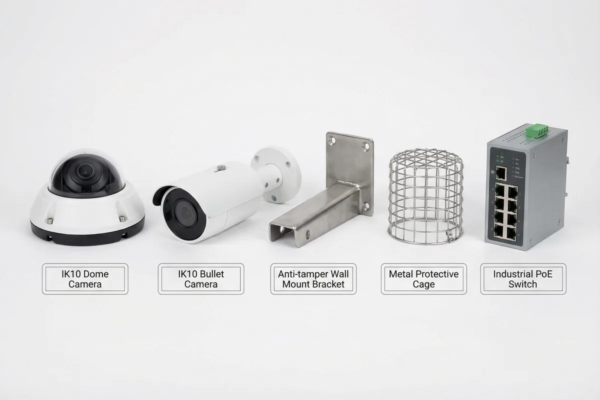
Product Category Overview
| Product | Primary Function | Key Differentiator | Typical Application | Selection Priority |
|---|---|---|---|---|
| IK10 Dome Camera | Close-range ID + tamper detection | IK10 housing + anti-tamper base + occlusion detection | Corridors, entrances, tunnels, platforms | Highest — primary evidence device |
| IK10 Bullet Camera | Long-range view + face capture | IK10 housing + long focal length + IR range | Perimeter, entrance lanes, outdoor poles | High — identification complement |
| Anti-tamper Mount | Structural retention | Security screws + anti-rotation pins + high pull-out strength | All camera installations | Critical — system is only as strong as its mount |
| Metal Protective Cage | Impact protection + cable hiding | Stainless steel construction + replaceable lens cover | Reachable zones, tunnels, parking garages | High — for zones below 3.5 m height |
| Industrial PoE Switch | Power + network distribution | Industrial temperature range + surge tolerance + ring protocol | All edge deployments | Critical — backbone of edge connectivity |
5.2 Interface Logic & Wiring
The interface logic diagram illustrates all physical and logical connections of a typical IK10 dome camera. Understanding these interfaces is essential for configuring alarm linkage, integrating with third-party systems, and troubleshooting connectivity issues. Each interface has specific electrical characteristics, protocol requirements, and protection needs that must be addressed during installation and commissioning.
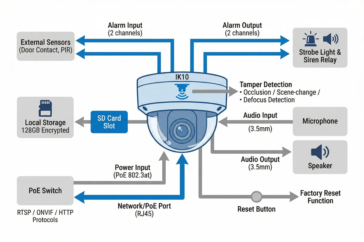
| Interface | Type | Specification | Protocol/Signal | Connected Device | Notes |
|---|---|---|---|---|---|
| Network/PoE | RJ45 | IEEE 802.3at (PoE+, 30W max) | RTSP, ONVIF, HTTP/HTTPS | Industrial PoE Switch | Cat6A shielded; max 100 m; SPD required for outdoor |
| SD Card | MicroSD slot | Up to 256 GB; Class 10 / U3 | Local file system (ext4) | MicroSD card | Encrypted storage recommended; auto-overwrite oldest |
| Alarm Input | Dry contact, 2 channels | 5–12 VDC, 10 mA max | N.O. or N.C. configurable | Door contact, PIR, tamper switch | Configure as N.C. for fail-safe (alarm on wire cut) |
| Alarm Output | Relay, 2 channels | 30 VDC / 1A max | Relay open/close | Strobe light, siren, door lock | Use external relay for high-current devices |
| Audio Input | 3.5 mm jack | Line level or mic level | Analog audio | Microphone | Check local regulations on audio recording |
| Audio Output | 3.5 mm jack | Line level, 200 mW max | Analog audio | Speaker (with amplifier) | Used for voice prompts and two-way intercom |
| Reset Button | Recessed button | Hold 10 s for factory reset | Hardware reset | N/A | Recessed to prevent accidental activation |
| Tamper Detection | Internal sensor | Software-based; configurable sensitivity | ONVIF event / proprietary | VMS alarm engine | Occlusion, scene-change, defocus; tune per zone |
5.3 Core Product Feature Comparison
The following comprehensive feature table covers all major IK10 camera selection parameters, organized by functional category. This table is designed to be used as a checklist during the procurement specification phase, ensuring that all critical requirements are captured and verified against vendor datasheets before purchase.
IK10 Camera Selection Criteria
| Category | Parameter | Minimum Requirement | Recommended Specification | Verification Method |
|---|---|---|---|---|
| Physical Protection | Impact Rating | IK10 (20 J) | IK10+ with metal cage option | IEC 62262 test certificate |
| Ingress Protection | IP66 | IP67 for wet/humid environments | IEC 60529 test certificate | |
| Mounting Base | Anti-pry, security screws | Anti-rotation pins + torque spec | Pull-out test ≥200 N | |
| Housing Material | PC/ABS with metal base | Full metal housing for highest risk | Material spec sheet | |
| Imaging Performance | Resolution | 4MP (2688×1520) | 8MP for critical ID zones | PPF measurement at design distance |
| WDR | ≥100 dB | ≥120 dB for high-contrast scenes | Backlight test with light meter | |
| Min Illumination | ≤0.01 lux (color) | ≤0.005 lux or starlight | Night-time face ID test | |
| IR Range | ≥20 m | ≥30 m with smart IR | IR illumination test at night | |
| Tamper Detection | Occlusion Detection | Configurable sensitivity | Day/night profiles; debounce timer | Tape/cloth test; alarm within 10 s |
| Scene Change Detection | Configurable threshold | Sensitivity tuning + exclusion zones | Camera re-aim test; alarm within 10 s | |
| Defocus Detection | Configurable sensitivity | Auto-recovery attempt | Vaseline test; alarm within 10 s | |
| Network & Storage | Video Codec | H.265 | H.265+ with Smart Codec | Bitrate measurement at target quality |
| Local Storage | MicroSD ≥64 GB | ≥128 GB encrypted | Disconnect uplink; verify local recording | |
| Protocols | ONVIF Profile S/T | ONVIF + proprietary SDK | ONVIF conformance certificate | |
| Environmental | Operating Temperature | -10°C to +50°C | -30°C to +60°C for outdoor | Datasheet + field test |
| Surge Protection | Built-in TVS diode | External SPD on cable entry | Surge test per IEC 61000-4-5 | |
| Corrosion Resistance | Standard paint finish | 316L stainless steel for coastal/industrial | Salt spray test certificate |
Industrial PoE Switch Selection Criteria
| Parameter | Minimum | Recommended | Notes |
|---|---|---|---|
| PoE Standard | IEEE 802.3af (15.4W) | IEEE 802.3at (30W) per port | Size for peak load including IR heaters |
| Total PoE Budget | Sum of camera draw × 1.2 | Sum of camera draw × 1.5 | Include strobe, intercom, other PoE devices |
| Operating Temperature | -10°C to +60°C | -40°C to +75°C | Outdoor cabinets can exceed 60°C in summer |
| Redundancy Protocol | RSTP | ERPS (G.8032) for <50 ms failover | Required for ring topology deployments |
| Surge Protection | 2 kV common mode | 4 kV per IEC 61000-4-5 Level 3 | Critical for outdoor and lightning-prone sites |
| Management | Web GUI + SNMP v2c | SNMP v3 + syslog + LLDP | Required for VMS health monitoring integration |
| Uplink Ports | 1× SFP (1G) | 2× SFP+ (10G) for dual uplink | Dual uplink required for ring topology |
| Mounting | DIN-rail | DIN-rail + wall mount options | Must fit in IP66-rated outdoor cabinet |